Universal Testing Machine (UTM)
A versatile machine that pulls, compresses or bends specimens while measuring force and extension. In construction labs it is mainly used for tensile testing of reinforcement bars to find yield strength, tensile strength and elongation.
- Construction materials testing
- Steel plants and rolling mills
- Infrastructure projects
- Fabrication and precast yards
- Academic and research labs
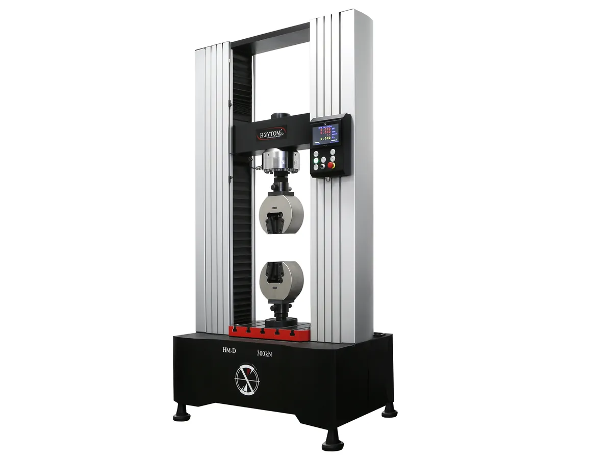
What is UTM?
A universal testing machine (UTM) can apply tension, compression and bending, which is why it is called 'universal'. A specimen is gripped between a fixed crosshead and a moving crosshead (or ram). As the crosshead moves, a load cell or hydraulic pressure sensor measures the force and an encoder or extensometer measures how much the specimen stretches.
Construction labs use UTMs mainly to test reinforcement steel (TMT bars) to IS 1786 using the tensile test method of IS 1608 (equivalent to ISO 6892-1). The machine plots force against extension, from which the 0.2% proof stress (or yield stress), ultimate tensile strength, the ratio of tensile strength to yield, and percentage elongation are worked out. Bend and rebend tests on bars, and tests on structural steel, wires and couplers, are also common.
Machines are either servo-hydraulic (high capacity, common for 400–1,000 kN rebar testing) or electromechanical screw-driven (precise speed control, common at lower capacities). Both need regular force verification, and an extensometer when proof stress or modulus is measured.
Used for
- Tensile test of reinforcement bars: proof stress, tensile strength, elongation
- Bend and rebend tests of rebars using mandrel attachments
- Tensile testing of structural steel plates, wires, strands and mechanical couplers
- Compression and flexure tests on concrete, bricks and tiles with suitable fixtures
- Testing of geosynthetics, pipes and other construction products
How it works
- 01
Specimen preparation
The bar is cut to length, its mass per metre measured to find the effective cross-sectional area, and gauge marks are made.
- 02
Gripping
The bar is clamped in serrated wedge jaws in the upper and lower crossheads, aligned on the machine axis.
- 03
Loading
The crosshead moves at a controlled rate; force rises as the bar stretches elastically.
- 04
Yield / proof stress
The extensometer measures strain so the 0.2% proof stress can be found by the offset method, or the yield point read directly.
- 05
Maximum force
Force reaches a peak (Fm) and the bar starts to neck; tensile strength = Fm ÷ area.
- 06
Fracture and elongation
After fracture the pieces are fitted together and the final gauge length measured to calculate percentage elongation.
Advantages
- One machine performs tension, compression and bending tests
- Records the full force–extension curve, not just the peak
- Automatic calculation of proof stress, tensile strength and elongation
- Controlled strain or stress rate gives reproducible results
- Wide range of grips and fixtures for different products
Limitations
- Higher cost and more complex than a CTM
- Accurate proof stress needs a calibrated extensometer; crosshead movement alone includes machine and grip compliance
- Grip slippage or jaw breaks can spoil tests
- Test speed must follow the standard closely, because strength values depend on strain rate
2 calibration procedures
Methods that use UTM
Keep every UTM in control: usage logs, calibration and maintenance schedules, and automatic blocking of overdue instruments.