Tensile Test of Reinforcement Bars (TMT / HSD Rebar)
A full-section length of rebar is pulled to failure in a universal testing machine. The yield (or 0.2% proof) load, maximum load and extension give the stresses and elongation, which are compared with the grade requirements of IS 1786.
- Construction materials
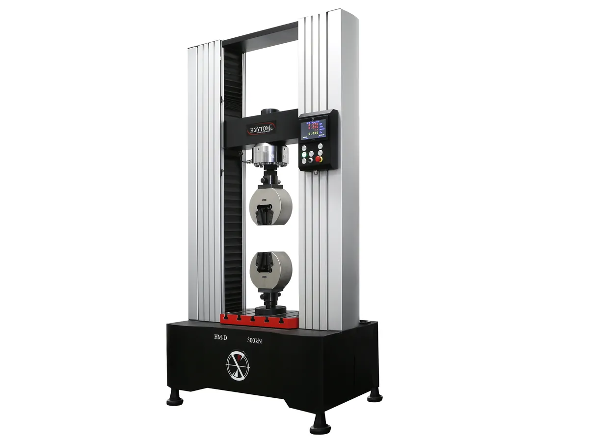
- Uniaxial tensile test on a universal testing machine
- UTM
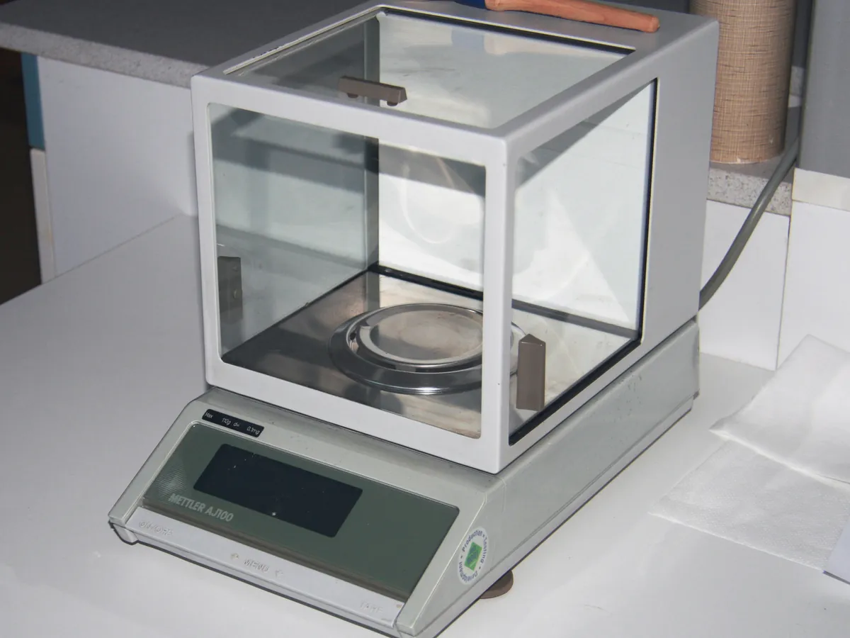
- Analytical balance
Reference: Typical method based on IS 1608 (Part 1) for the test and IS 1786 for the requirements; ASTM A370 / ISO 6892-1 are similar. Always follow the current editions and your approved SOP.
Why this method works
When steel is pulled, it first stretches elastically: stress is proportional to strain and the bar would return to its length if unloaded. At the yield point (or, for steels without a clear yield, the 0.2% proof stress) it starts to deform permanently. It then strain-hardens up to the maximum force, which gives the tensile strength, before necking and breaking. Rebar is tested in full section, so stress is calculated from the force divided by the nominal cross-sectional area of the bar size (for example 201.1 mm² for 16 mm). The ratio of tensile strength to yield stress and the elongation show ductility, which lets a structure bend and warn before it fails, especially in earthquakes.
Instruments used
Reagents & standards
| Reagent | Grade / specification |
|---|---|
| Test piece | Straight length of bar in the as-rolled condition, long enough for the grips plus the gauge length (often about 500–600 mm, or as your SOP states) |
| Gauge marking | Punch or scribe marks for the original gauge length, e.g. 5.65 √S₀ (= 5 d for round bars) |
| Extensometer | Class suited to proof-stress measurement, where 0.2% proof stress is required |
Preparing the sample
- 01
Identify
Record heat number, grade, size and sample ID.
- 02
Mass per metre
Weigh and measure the bar to check mass per metre.
- 03
Mark gauge
Mark the gauge length, e.g. 5.65 √S₀ (≈ 80 mm for 16 mm).
- 04
Grip
Fit the bar in V-grips; attach the extensometer if used.
- 05
Pull
Load at the rate in IS 1608 until fracture.
- 06
Measure
Fit the broken pieces together and measure final gauge length.
Procedure
- 1Cut the test piece from the bar without heating or straightening it in a way that would change its properties. Do not machine the ribs.
- 2Weigh the piece and measure its length. Calculate the mass per metre and compare it with the nominal value for the size (for 16 mm, about 1.58 kg/m) within the tolerance in IS 1786.
- 3Mark the original gauge length L₀ along the bar, for example 5.65 √S₀. For a 16 mm bar, √201.1 × 5.65 ≈ 80 mm.
- 4Grip the bar in suitable wedge grips so that it is loaded along its axis. Attach the extensometer if the 0.2% proof stress is to be measured.
- 5Apply load at a controlled rate within the limits of IS 1608 (stress rate in the elastic range, then strain rate in the plastic range). Record the force–extension curve.
- 6Record the yield or 0.2% proof force and the maximum force. Remove the extensometer before necking if the instruction requires it.
- 7After fracture, fit the two pieces together and measure the final gauge length L_u. If the fracture is outside the middle part of the gauge length or at a grip, follow the validity rules in IS 1608.
Standard preparation
- 1UTM force verified (for example to Class 1 or better per IS 1828 / ISO 7500-1) within the calibration interval.
- 2Extensometer verified within its interval (for example IS 12872 / ISO 9513) if proof stress is measured.
Notes for analysts
- Use the nominal area, not a measured diameter. Ribbed bars have no single true diameter, and IS 1786 bases stress on nominal area.
- A bar that is under-weight (low mass per metre) has less steel than its nominal area suggests, so it will carry less load even if the calculated stress passes.
- Grade 'D' bars have extra ductility requirements and are preferred in earthquake-resistant design.
Method parameters (typical)
| Area used for stress | Nominal cross-sectional area of the bar size, e.g. 201.1 mm² for 16 mm |
|---|---|
| Gauge length | 5.65 √S₀ (proportional), ≈ 80 mm for 16 mm bar |
| Loading rate | Within the stress-rate / strain-rate limits of IS 1608 (Part 1) |
| Results | Yield or 0.2% proof stress, tensile strength, TS/YS ratio, % elongation (and total elongation at maximum force for D grades) |
| Temperature | Room temperature, typically 10–35 °C |
System suitability & sequence
| Parameter | Limit |
|---|---|
| Fracture position | Within the gauge length and away from the grips, or as the validity rules allow |
| Grip slippage | No slipping visible on the force–extension curve |
| Machine status | Force calibration and extensometer verification in date |
Typical sequence
- 1Identify and measure the test piece
- 2Check mass per metre
- 3Mark gauge length
- 4Run the tensile test to fracture
- 5Measure final gauge length
- 6Calculate stresses, ratio and elongation; compare with IS 1786 grade
Calculation with a worked example
Where
- Re
- Yield stress or 0.2% proof stress (MPa)
- Rm
- Tensile strength = maximum force ÷ nominal area (MPa)
- S₀
- Nominal cross-sectional area (mm²)
- L₀
- Original gauge length (mm)
- L_u
- Final gauge length after fracture (mm)
Given
- Bar
- 16 mm Fe 500, nominal area S₀ = 201.1 mm²
- 0.2% proof force
- 108.5 kN
- Maximum force
- 125.0 kN
- Gauge length
- L₀ = 80.0 mm; L_u = 94.4 mm
Working
- 1Re = 108 500 N ÷ 201.1 mm² = 539.5 MPa
- 2Rm = 125 000 N ÷ 201.1 mm² = 621.6 MPa
- 3TS/YS = 621.6 ÷ 539.5 = 1.15
- 4Elongation = (94.4 − 80.0) ÷ 80.0 × 100 = 18.0%
- 5
Compare with typical Fe 500 requirements: Re ≥ 500 MPa ✓, TS/YS ≥ 1.08 ✓, elongation ≥ 12% ✓
0.2% proof stress 539.5 MPa, tensile strength 621.6 MPa, TS/YS 1.15, elongation 18.0% — meets the typical IS 1786 Fe 500 requirements (and would also meet the typical Fe 500D ratio and elongation values).
What result passes
- Typically, per IS 1786: Fe 500 — 0.2% proof stress / yield stress at least 500 MPa; tensile strength at least 1.08 × the actual yield stress (and not less than the minimum TS for the grade); elongation at least 12%.
- Typically, per IS 1786: Fe 500D — yield at least 500 MPa; TS/YS at least 1.10 (and not less than the minimum TS for the grade); elongation at least 16%, plus a minimum total elongation at maximum force.
- Mass per metre within the tolerance in IS 1786 for the bar size; bend and rebend tests (separate) must also pass.
- Check the current edition of IS 1786 for the exact values for each grade.
Validation parameters (ICH Q2(R2))
| Parameter | Typical requirement |
|---|---|
| Approach | Standard method; accredited labs show competence by proficiency testing and measurement uncertainty estimation |
| Traceability | Force and extension measurements traceable through UTM and extensometer calibration |
| Uncertainty | Estimate for Re, Rm and elongation; consider it when results are close to limits |
Run this method in LimsPulse: specifications and STPs under version control, results calculated and checked against limits, and a signed Certificate of Analysis.