Thin-Layer Chromatography (TLC)
Separates compounds as a solvent climbs up a thin layer of adsorbent on a glass, aluminium or plastic plate. Simple and cheap; used in pharma QC mainly for identification and limit tests for related substances.
- Pharmaceutical
- Herbal & natural products
- Chemicals
- Forensic
- Education
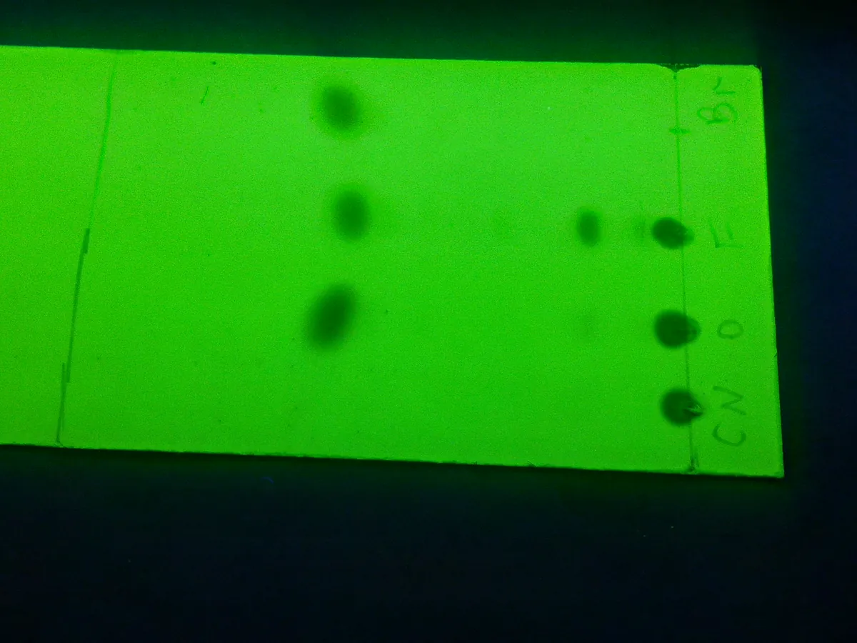
How TLC works
On silica gel TLC, separation is mainly by adsorption: polar compounds bind more strongly to the polar silica surface and move less, so they have lower Rf values; non-polar compounds travel further. Making the mobile phase more polar increases Rf values for all components.
The path of a sample
- 01
Prepare chamber
Add mobile phase to a depth below the application line, line the tank with filter paper and close it to saturate (often 30 minutes or as the method states).
- 02
Apply spots
Apply small, equal volumes of test and reference solutions on a pencil line about 1.5–2 cm from the bottom edge.
- 03
Develop
Place the plate in the tank and let the solvent rise to a marked distance (e.g. 10–15 cm or three-quarters of the plate).
- 04
Dry
Remove the plate, mark the solvent front immediately and dry in air or a stream of warm air.
- 05
Visualise
View under UV light (254 or 365 nm) or spray or dip with a reagent, then heat if required.
- 06
Evaluate
Measure Rf values and compare spot position, colour and intensity with the references.
Main parts and what they do
TLC plates
Glass, aluminium or plastic sheets coated with silica gel, alumina, cellulose or reversed-phase material, with or without fluorescent indicator.
Developing chamber
Glass tank with a tight lid that holds the mobile phase and saturated vapour; twin-trough chambers save solvent.
Sample applicator
Calibrated glass capillaries or microsyringes; automated band applicators for HPTLC.
UV viewing cabinet
Dark cabinet with 254 nm and 365 nm lamps for viewing spots.
Spray or dipping device
Applies visualisation reagents evenly across the plate.
Plate heater or oven
Activates plates before use and develops colour after spraying certain reagents.
Camera / documentation system
Records an image of the plate as the raw data for the test.
Terms every analyst should know
Rf value
Retardation factor = distance from origin to spot centre ÷ distance from origin to solvent front. Always between 0 and 1.
Chamber saturation
Filling the tank atmosphere with solvent vapour before development gives straighter fronts and more reproducible Rf values.
Stationary phase
Usually silica gel 60, often with a fluorescent indicator (F254) so UV-absorbing spots appear dark on a green background.
Mobile phase selection
Aim for Rf values roughly between 0.2 and 0.8. Increase polarity if spots stay near the origin; decrease it if they run with the front.
Visualisation
UV quenching at 254 nm, fluorescence at 365 nm, iodine vapour, or chemical reagents such as ninhydrin (amines), anisaldehyde–sulphuric acid or Dragendorff (alkaloids).
System suitability for TLC
Pharmacopoeial tests often require two named reference spots to be clearly separated, or a diluted reference to be visible, before the plate is valid.
Keep every TLC in control: usage logs, calibration and maintenance schedules, and automatic blocking of overdue instruments.