Particulate Matter (PM10 / PM2.5) Sampler
Draws a known volume of ambient air through a size-selective inlet and a filter so that the mass of PM10 or PM2.5 particles collected can be weighed and expressed as µg/m³.
- Environmental monitoring agencies and pollution control boards
- Environmental consultancies
- Mining, cement, power and steel
- Research institutions
- Construction and infrastructure projects
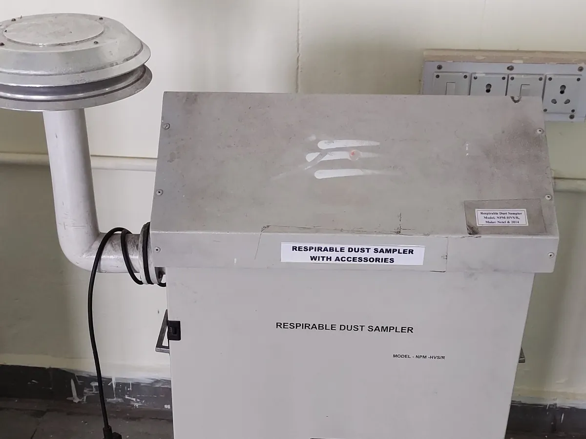
How PM sampler works
Particles are separated by aerodynamic size in the inlet. The pump draws air at a set flow rate so that the inlet cut-point is correct, and the filter collects all particles that pass the inlet. Concentration = mass collected ÷ volume of air sampled.
The path of a sample
- 01
Inlet
Ambient air enters through a rain-proof inlet designed for a specific flow rate.
- 02
Size separation
An impactor or cyclone removes particles larger than the cut-point (10 µm or 2.5 µm).
- 03
Filtration
Remaining particles are collected on a pre-weighed filter.
- 04
Flow control
A pump with a mass flow controller or critical orifice holds a constant flow; total volume is logged.
- 05
Gravimetry
The filter is conditioned and re-weighed; mass gain ÷ air volume gives µg/m³.
Main parts and what they do
Size-selective inlet
Impactor or cyclone that removes coarse particles above the cut-point.
Filter holder / cassette
Holds the filter flat and sealed so all air passes through it.
Filters
Glass fibre (high volume) or PTFE membrane, 47 mm (low volume).
Pump (blower or vacuum pump)
Draws air through the inlet and filter.
Flow controller and sensor
Mass flow controller, venturi or orifice that holds the flow at the design value.
Timer and data logger
Records run time, flow, ambient temperature and pressure.
Weather-proof housing
Protects the electronics and filter during outdoor operation.
Terms every analyst should know
Aerodynamic diameter
The diameter of a unit-density sphere that settles at the same speed as the particle. Inlets separate particles by this property, not by their physical size.
Cut-point (D50)
The particle size at which the inlet lets through 50% of particles. A PM2.5 inlet is designed so D50 = 2.5 µm at its design flow rate; a wrong flow shifts the cut-point.
Design flow rate
Typical values are about 1.1 m³/min for high-volume PM10 samplers and 16.67 L/min for low-volume PM2.5 samplers.
Actual vs standard conditions
Flow can be expressed at actual site temperature and pressure or corrected to standard conditions. The reporting basis must follow the applicable standard.
Filter conditioning
Filters are equilibrated in a controlled room (typically about 20–23 °C and 30–40% RH, or as per the applicable guidance) for at least 24 hours before each weighing.
Keep every PM sampler in control: usage logs, calibration and maintenance schedules, and automatic blocking of overdue instruments.