Compression Testing Machine (CTM)
A rigid hydraulic press that crushes concrete cubes, cylinders and cement mortar cubes at a controlled loading rate and records the maximum load. The basic instrument of every concrete and cement lab.
- Construction materials testing
- Ready-mix concrete plants
- Cement plants
- Precast concrete
- Infrastructure and road projects
- Academic and research labs
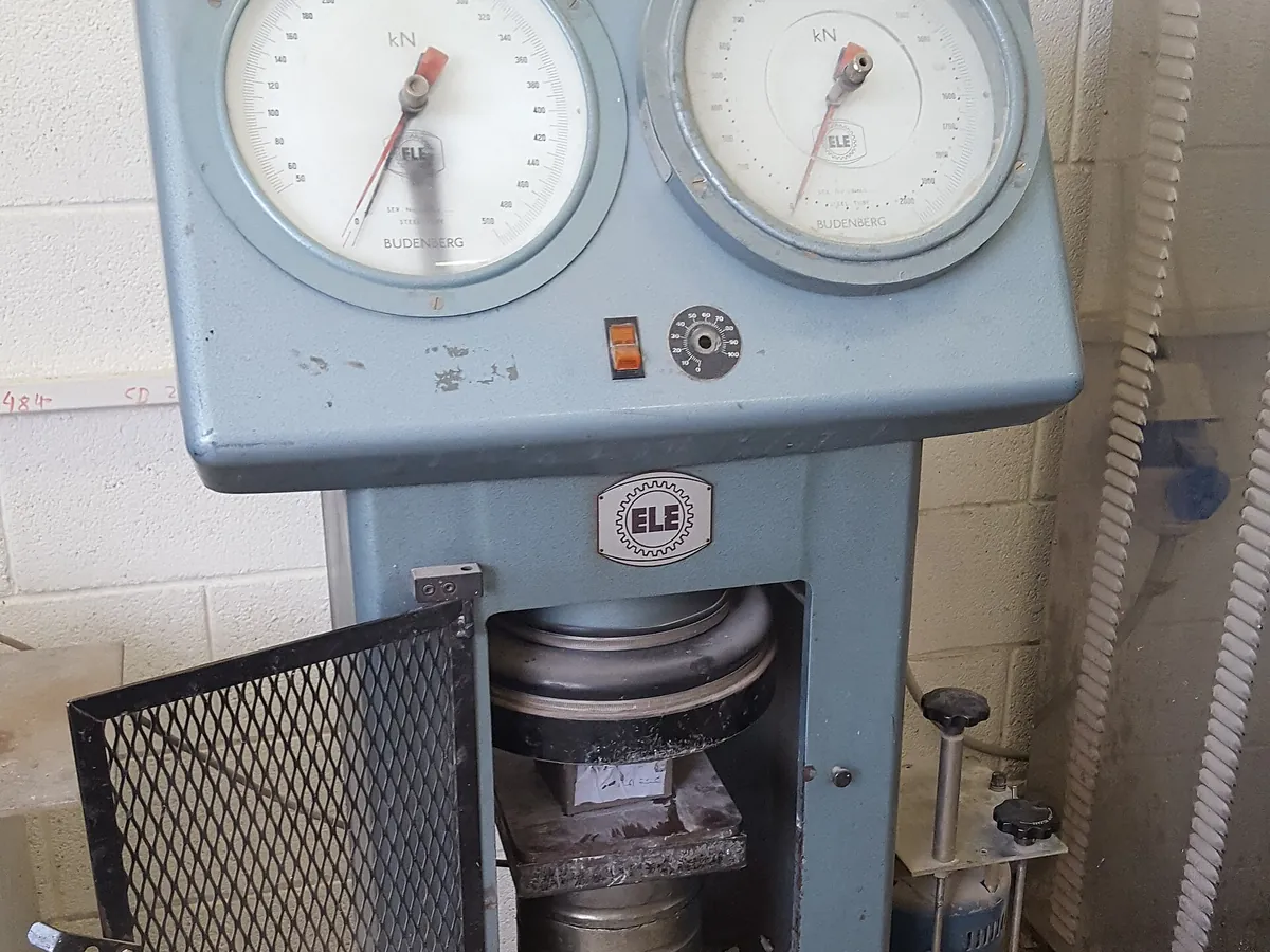
How CTM works
Compressive strength is force divided by area. The machine applies an increasing axial load at a constant rate through parallel platens, one of which is spherically seated so it aligns with the specimen face. The peak force at failure is recorded and divided by the cross-sectional area of the specimen.
The path of a sample
- 01
Specimen placed
The cube is placed centrally with its cast faces against the platens (the trowelled top face is not loaded).
- 02
Seating
The upper platen's spherical seat tilts to sit evenly on the specimen face before loading starts.
- 03
Hydraulic loading
The pump drives the ram so that stress rises at the set pace rate, e.g. about 14 N/mm² per minute for concrete under IS 516.
- 04
Force measurement
A pressure transducer or load cell converts hydraulic pressure or strain into force, shown on the display.
- 05
Failure and peak hold
The specimen cracks and the load drops; the controller detects the drop and holds the peak value.
- 06
Result
Strength = peak load ÷ loaded area, reported to the nearest 0.1 or 0.5 N/mm² as the standard requires.
Main parts and what they do
Loading frame
A stiff steel frame (two or four columns) that resists the reaction force without noticeable deflection.
Hydraulic ram (piston and cylinder)
Converts oil pressure into the force applied to the specimen.
Hydraulic power pack
Electric motor, pump, oil tank and valves that deliver controlled oil flow to the ram.
Upper platen with spherical seat
Self-aligning hardened platen that sits flat on the specimen face.
Lower platen
Fixed hardened platen, usually engraved with centring circles or squares for placing cubes.
Distance pieces / spacers
Steel blocks that reduce the daylight opening so specimens of different heights can be tested with a short ram stroke.
Load sensor
Pressure transducer in the hydraulic line or a load cell under the platen; its signal is converted to force.
Controller and display
Sets pace rate, shows live load and peak load, calculates strength and stores results.
Safety guard
A mesh or polycarbonate guard around the platens that stops concrete fragments flying out.
Terms every analyst should know
Pace rate (loading rate)
The rate at which stress or load is increased. Too fast gives falsely high strength; too slow gives low strength. IS 516 typically specifies about 14 N/mm²/min for concrete; ASTM C39 about 0.25 ± 0.05 MPa/s for cylinders.
Spherical seating
A ball-and-socket upper platen that self-aligns with the specimen at the start of the test, then locks under load so force stays axial.
Machine class
IS 1828 Part 1 / ISO 7500-1 grade machines into classes (0.5, 1, 2, 3) by their relative error of indication and repeatability. Class 1 (about ±1%) is the usual minimum for concrete testing.
Verified range
The span of forces over which the machine has been shown to meet its class, typically from about 10–20% to 100% of each range. Loads below the verified range should not be reported.
Failure pattern
A satisfactory cube failure shows roughly equal cracking on all four faces (an hourglass shape). Unusual patterns point to poor specimens or machine misalignment.
Keep every CTM in control: usage logs, calibration and maintenance schedules, and automatic blocking of overdue instruments.