Proctor Compaction Apparatus
A cylindrical mould and a rammer of fixed mass and drop height used to compact soil at different water contents and find its maximum dry density (MDD) and optimum moisture content (OMC).
- Geotechnical testing
- Road and highway construction
- Railways and airports
- Dams and embankments
- Construction materials testing
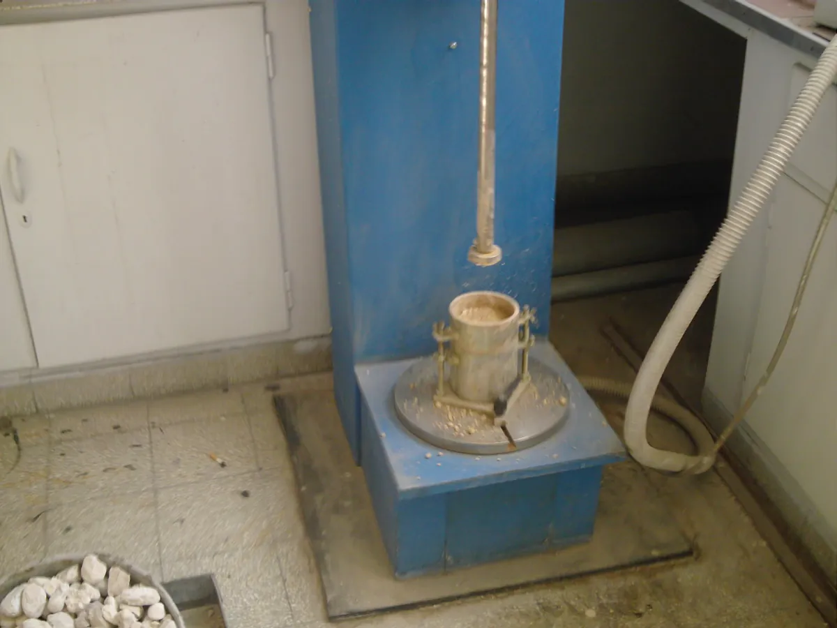
How Proctor apparatus works
Adding water lubricates soil particles so they pack more densely under a given compactive effort, until the voids fill with water and further water pushes particles apart. Dry density therefore rises to a maximum at the optimum moisture content and then falls. Compactive energy = rammer mass × g × drop height × blows per layer × layers ÷ mould volume.
The path of a sample
- 01
Prepare soil
Air-dried soil passing the specified sieve (e.g. 19 mm or 4.75 mm) is mixed with a known amount of water and left to mature.
- 02
Compact in layers
Soil is placed in the mould with its collar in three (light) or five (heavy) equal layers, each given 25 evenly spread blows.
- 03
Trim and weigh
The collar is removed, the soil trimmed level with the mould top, and the mould plus soil weighed.
- 04
Moisture content
A sample from the middle of the specimen is oven-dried to find water content.
- 05
Repeat
The test is repeated at increasing water contents until the wet mass starts to fall.
- 06
Plot
Dry density = bulk density ÷ (1 + w) is plotted against w; the peak gives MDD and OMC.
Main parts and what they do
Compaction mould
Cylinder of typically 1000 cm³ (100 mm diameter × 127.3 mm high) or 2250 cm³ (150 mm diameter) for coarser soils.
Detachable collar
Extension about 60 mm high fitted above the mould while compacting.
Base plate
Detachable plate the mould is clamped to.
Light rammer
Typically 2.6 kg with a 50 mm diameter face and 310 mm free fall (IS 2720 Part 7).
Heavy rammer
Typically 4.9 kg with a 50 mm face and 450 mm free fall (IS 2720 Part 8).
Guide sleeve
Tube that controls the drop height and keeps the fall vertical.
Automatic compactor (optional)
Motor-driven rammer with a rotating base that distributes blows evenly and counts them.
Ancillaries
Balance, sieves, straight edge, mixing tray, moisture tins, oven, sample extruder.
Terms every analyst should know
Maximum dry density (MDD)
The highest dry density reached for a given compactive effort.
Optimum moisture content (OMC)
The water content at which MDD occurs.
Compactive energy
About 593 kJ/m³ for IS light compaction (2.6 kg × 9.81 × 0.31 m × 75 blows ÷ 0.001 m³) and about 2,700 kJ/m³ for heavy compaction.
Zero air voids line
The theoretical dry density if all voids were filled with water; the compaction curve should lie below it.
Relative compaction
Field dry density as a percentage of laboratory MDD; used to accept field compaction.
Keep every Proctor apparatus in control: usage logs, calibration and maintenance schedules, and automatic blocking of overdue instruments.