Airborne particle counter
Counts and sizes airborne particles, typically at ≥0.5 µm and ≥5.0 µm, by measuring light scattered as each particle passes through a laser beam. Used to classify clean rooms and to monitor non-viable particles in Grades A–D.
- Pharmaceutical
- Biotech
- Medical devices
- Semiconductors
- Hospitals
- Aerospace
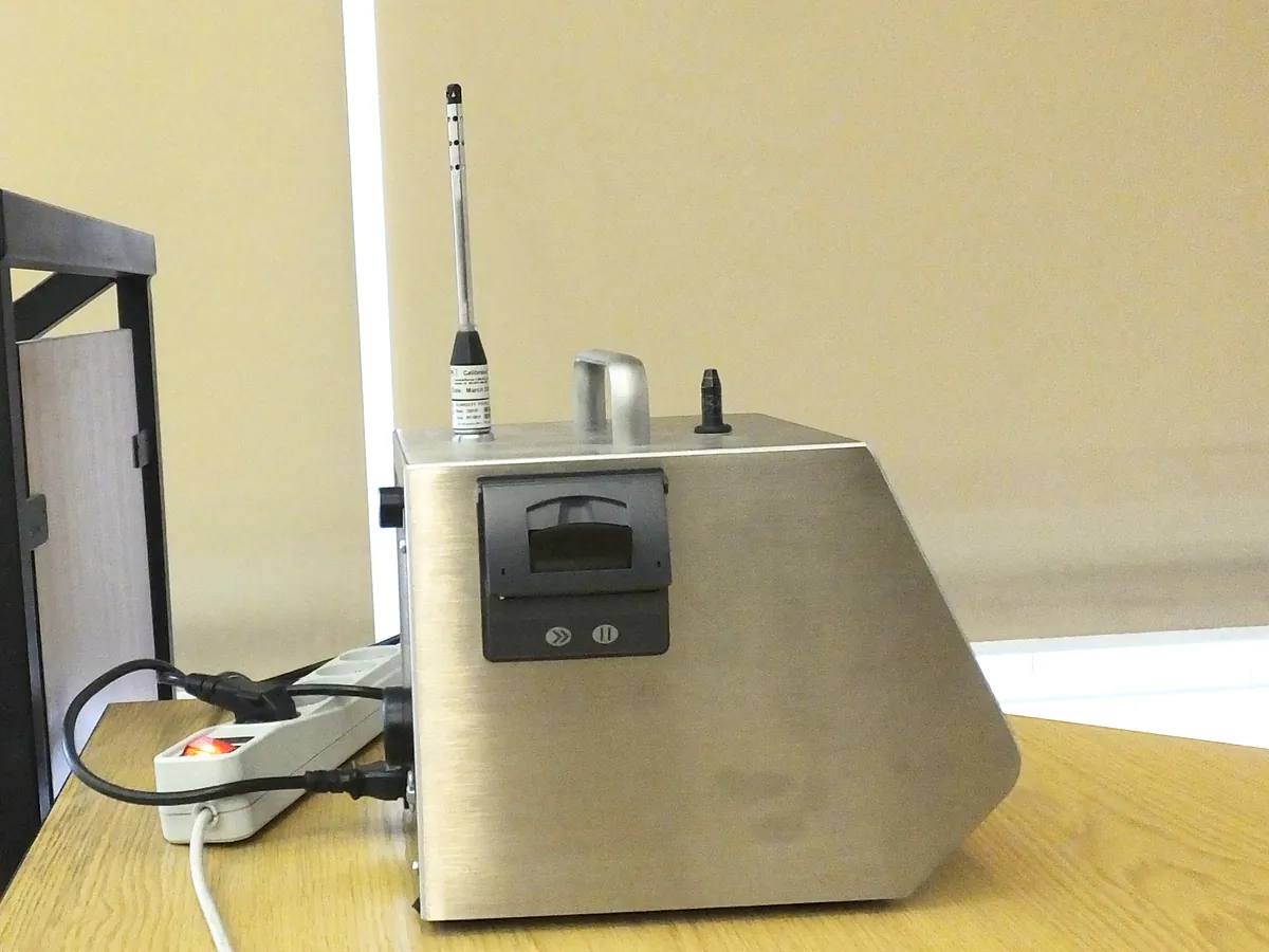
How Particle counter works
Air is drawn through an isokinetic probe into a sensor where a laser diode lights a small view volume. Each particle scatters light in proportion to its size; a photodetector converts each flash into an electrical pulse. Pulse height is compared with threshold voltages set during calibration with certified polystyrene latex (PSL) spheres, and pulses are counted in each size channel. Count ÷ volume sampled = particles per m³.
The path of a sample
- 01
Sample inlet
An isokinetic probe takes air at the same speed as the surrounding unidirectional flow.
- 02
Flow control
A pump and flow sensor hold the sample flow at the nominal rate, e.g. 28.3 L/min.
- 03
Illumination
Particles pass one at a time through a laser beam in the sensor.
- 04
Scatter detection
Scattered light is collected onto a photodetector and turned into pulses.
- 05
Sizing & counting
Pulse heights are sorted into size channels using thresholds set with PSL spheres.
- 06
Report
Counts are converted to particles per m³ and compared with grade limits.
Main parts and what they do
Isokinetic sample probe
Inlet shaped to match the air speed of unidirectional flow.
Sample tubing
Connects remote probes to the sensor; as short and straight as possible.
Laser diode and optics
Light the view volume and collect scattered light.
Photodetector and pulse analyser
Convert light pulses to signals and sort them into size channels.
Pump and flow sensor
Hold the sample flow at the nominal rate; checked at calibration.
Exhaust HEPA filter
Cleans the air leaving the counter so it does not contaminate the room.
Display, memory and printer / software
Set up locations and volumes, store results and export them.
Purge (zero count) filter
HEPA filter fitted to the inlet to confirm the counter reads zero.
Terms every analyst should know
Cumulative counts
Results are reported as particles equal to or larger than a size (e.g. ≥0.5 µm), so the ≥0.5 µm count includes the ≥5.0 µm particles.
Isokinetic sampling
Sampling at the same air speed as the surrounding flow, so large particles are not over- or under-collected.
Counting efficiency
The fraction of particles of a given size that the counter detects. ISO 21501-4 typically expects about 50% at the minimum detectable size and close to 100% at 1.5–2 times that size.
Coincidence loss
At very high concentrations two particles may be in the beam at once and counted as one larger particle. The maximum concentration is stated by the manufacturer.
Sample volume
ISO 14644-1 sets a minimum volume per location so that at least 20 particles could be counted at the class limit; for Grade A at ≥5.0 µm this leads to sampling 1 m³.
Tubing losses
Particles ≥5.0 µm settle in long or bent tubing. Annex 1 expects tubing length and bends to be minimised and justified.
Keep every Particle counter in control: usage logs, calibration and maintenance schedules, and automatic blocking of overdue instruments.