Temperature mapping
Places calibrated thermocouples throughout the chamber and inside load items to find the coldest point and prove every position reaches sterilising temperature for long enough, expressed as an F0 value.
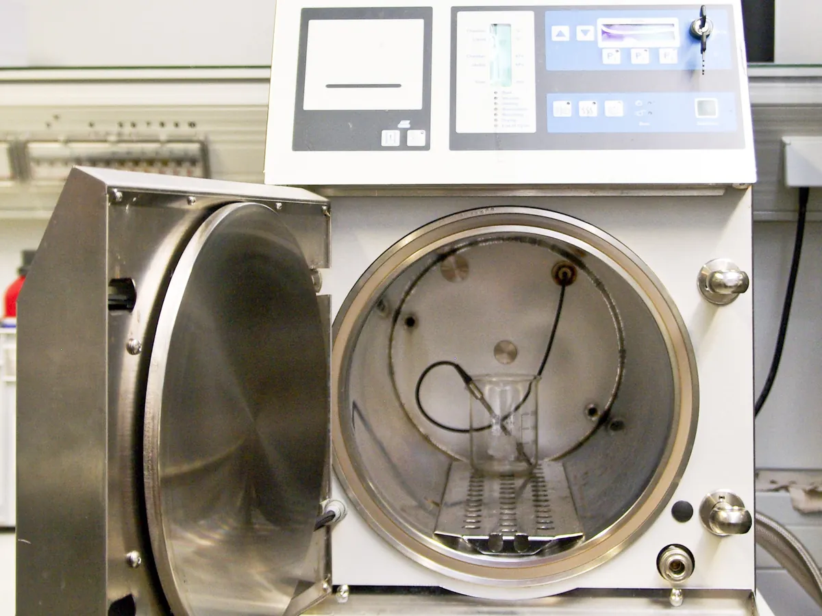
Why this is checked
The controller probe measures only one point, usually the drain. Mapping proves that the whole chamber (heat distribution) and the inside of each load item (heat penetration) reach and hold the sterilisation temperature, and identifies the cold spot used for routine monitoring.
At initial qualification (three consecutive runs per load pattern), then typically annually and after major repair, relocation or a change in load pattern, as defined in your validation SOP.
Learn how the Autoclave worksStandards & tools
- Calibrated thermocouples (e.g. type T) or wireless data loggers, typically 10–20 probes, calibrated before and after the study
- Calibrated temperature reference (dry-block calibrator) traceable to national standards
- Validated data acquisition system or logger software
Prerequisites
- Autoclave IQ complete and controller probe and pressure gauge calibrated
- Bowie-Dick and vacuum leak tests passed (pre-vacuum autoclaves)
- Thermocouples checked against the reference at 121 °C before use (typically within ±0.5 °C)
- Load patterns to be validated are defined and documented with photographs or drawings
Step by step
- 1Empty chamber (heat distribution): place probes at the geometric centre, corners, near the door and next to the drain/controller probe; run three cycles at 121 °C.
- 2Loaded chamber (heat penetration): place probes inside the slowest-heating items, such as the centre of the largest media bottle or the middle of a wrapped pack, plus one at the drain.
- 3Run the cycle and record every probe at a fixed interval (e.g. every 10 seconds to 1 minute).
- 4From the data, find the equilibration time (time from the drain reaching set point until all probes are within the band) and the temperature range during the hold period.
- 5Calculate the F0 at each probe and identify the cold spot (the probe with the lowest F0).
- 6Repeat for three consecutive runs per load pattern and check the probes against the reference again after the study.
Example observation table
| Probe | Location | Min. during hold (°C) | Max. during hold (°C) | F0 (min) |
|---|---|---|---|---|
| TC-01 | Drain (reference) | 121.4 | 122.3 | 21.6 |
| TC-02 | Chamber centre | 121.6 | 122.4 | 22.0 |
| TC-03 | Top front, near door | 121.4 | 122.2 | 21.3 |
| TC-04 | Bottom rear | 121.5 | 122.3 | 21.5 |
| TC-05 | Inside 1000 mL media bottle (centre) | 121.3 | 122.1 | 17.9 |
| TC-06 | Inside 500 mL media bottle | 121.4 | 122.2 | 19.6 |
How to calculate the result
- Cold spot TC-05, readings every 1 minute during the 15-minute hold: 121.3, 121.6, 121.8, 121.9, 122.0, 122.0, 122.1, 122.0, 122.1, 122.0, 121.9, 122.0, 121.8, 121.7, 121.9 °C
- At 121.3 °C: 10^((121.3 − 121.1) / 10) = 10^0.02 = 1.047; at 122.0 °C: 10^0.09 = 1.230
- Summing the 15 one-minute terms gives 17.94
- F0 at the cold spot ≈ 17.9 minutes (passes a typical minimum of 15 minutes; heat-up and cool-down add a little more lethality)
Pass if
- All probes within the sterilisation band during the hold, typically set temperature to set temperature +3 °C (121–124 °C).
- Equilibration time typically not more than 15 seconds for small chambers and 30 seconds for larger chambers (per EN 285 approach), or as defined in your protocol.
- F0 at the cold spot not less than the validated minimum, typically 15 minutes for culture media and materials.
- Results reproducible over three consecutive runs.
What to do
- Do not use the failing cycle or load pattern for routine sterilisation.
- Check the thermocouple calibration and placement, then the air removal, steam supply and drain.
- Change the load pattern (fewer or smaller items, more spacing) or extend the exposure time, then re-map.
- Raise a deviation and assess loads sterilised since the last successful mapping.
Other Autoclave calibrations
LimsPulse schedules this calibration, records the result against limits, and blocks the instrument everywhere if it fails or goes overdue.