Kinematic Viscosity by Glass Capillary Viscometer
The time taken for a fixed volume of oil to flow under gravity through a calibrated glass capillary at a closely controlled temperature is measured. Kinematic viscosity = viscometer constant × flow time.
- Petroleum, oil & gas
- Glass capillary viscometer
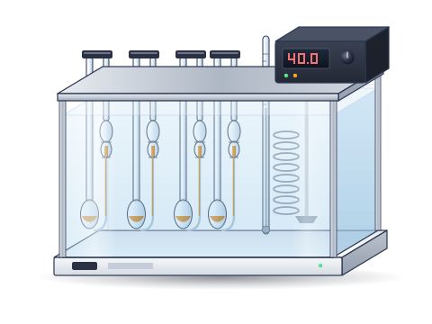
- Viscosity bath
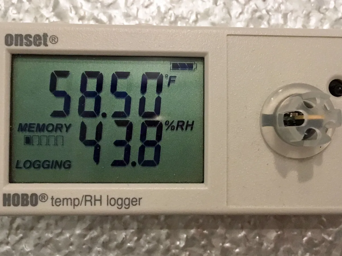
- Thermometer / logger
Reference: Typical method based on ASTM D445, ISO 3104 and IS 1448 Part 25, with viscometers to ASTM D446. Follow the current edition.
Why this method works
In a capillary viscometer, the liquid flows under its own weight. For a Newtonian liquid and a flow time long enough that kinetic-energy effects are negligible, the flow time is directly proportional to the kinematic viscosity. The proportionality constant C is found for each viscometer by calibration with certified viscosity standards. Because viscosity changes strongly with temperature, the bath is held within ±0.02 °C.
Instruments used
Reagents & standards
| Reagent | Grade / specification |
|---|---|
| Rinse solvent | Petroleum spirit, heptane or toluene to remove oil |
| Drying solvent | Acetone or another volatile solvent, followed by dry filtered air |
| Viscosity check standard | Certified viscosity standard for periodic checks |
Preparing the sample
- 01
Mix
Shake or invert the sample to make it uniform.
- 02
Filter
Remove particles through a fine screen or sintered glass filter.
- 03
Select viscometer
Choose a size giving a flow time of at least 200 s.
- 04
Charge and equilibrate
Fill, hang vertically and wait about 30 min.
- 05
Time twice
Measure two flow times and calculate.
Procedure
- 1Mix the sample well. Warm waxy or very viscous samples as the method allows, then let them cool to near test temperature.
- 2Filter through a fine screen (for example 75 µm) if particles may be present.
- 3Choose a calibrated viscometer whose range gives a flow time of at least 200 s at the test temperature.
- 4Charge the viscometer as its type requires and hang it vertically in the bath at 40.00 °C (or 100.00 °C).
- 5Allow about 30 minutes to reach temperature.
- 6Draw the sample above the upper timing mark, release, and time the meniscus from the upper to the lower mark.
- 7Repeat to obtain a second flow time.
- 8Calculate each viscosity and check that the two agree within the determinability for the product type; report the mean.
Standard preparation
- 1Run a certified viscosity standard in a routine viscometer at the SOP frequency; the result should be within the certificate tolerance.
Notes for analysts
- 1 mm²/s = 1 centistoke (cSt).
- Opaque samples (used engine oils, fuel oils) need reverse-flow viscometers.
- Viscosities at 40 °C and 100 °C are used to calculate the viscosity index (ASTM D2270).
- Safety: bath oil at 100 °C causes burns; cleaning solvents are flammable and must be used in a fume hood away from the heater.
Method parameters (typical)
| Test temperature | 40.00 °C and/or 100.00 °C for lubricants (40 °C for diesel) |
|---|---|
| Bath control | ±0.02 °C (15–100 °C) |
| Thermometer | Calibrated, graduated to 0.02 °C or digital equivalent |
| Minimum flow time | 200 s |
| Equilibration | About 30 min (longer for viscous samples) |
| Timer | Resolution 0.1 s; verified against a reference time signal |
| Reporting | Mean of two determinations, to four significant figures, with temperature |
System suitability & sequence
| Parameter | Limit |
|---|---|
| Determinability | Two values from one filling agree within the limit for the product type in the current D445 (about 0.1–0.2% for many oils) |
| Check standard | Within certificate tolerance at the SOP frequency |
Typical sequence
- 1Bath temperature check
- 2Check standard (per SOP)
- 3Samples
- 4Clean and dry viscometers
Calculation with a worked example
Where
- ν
- Kinematic viscosity (mm²/s)
- C
- Viscometer constant at the test temperature (mm²/s²)
- t
- Flow time (s)
- η
- Dynamic viscosity (mPa·s)
- ρ
- Density at the test temperature (g/cm³)
Given
- Sample
- Hydraulic oil labelled ISO VG 46, at 40.00 °C
- Viscometer constant C
- 0.1035 mm²/s²
- Flow times t1 / t2
- 412.8 s / 413.2 s
- Density at 40 °C
- 0.861 g/cm³
Working
- 1
ν1 = 0.1035 × 412.8 = 42.72 mm²/s
- 2
ν2 = 0.1035 × 413.2 = 42.77 mm²/s
- 3Difference = (42.766 − 42.725) ÷ 42.746 × 100 ≈ 0.10% (unrounded values) — within determinability
- 4
Mean ν = 0.1035 × 413.0 = 42.75 mm²/s
- 5
Dynamic viscosity η = 42.75 × 0.861 = 36.81 mPa·s
Kinematic viscosity at 40 °C = 42.75 mm²/s (dynamic viscosity 36.81 mPa·s)
What result passes
- ISO VG grades allow ±10% around the mid-point at 40 °C: ISO VG 46 = 41.4 to 50.6 mm²/s, so 42.75 mm²/s conforms (ISO 3448).
- For in-service oils, a change of more than about ±10% from the new-oil value is a common alert level (as set in the condition-monitoring programme).
Validation parameters (ICH Q2(R2))
| Parameter | Typical requirement |
|---|---|
| Trueness | Certified viscosity standards within tolerance |
| Precision | Determinability, repeatability and reproducibility from the current D445 for the product type |
| Temperature | Bath verified within ±0.02 °C |
Run this method in LimsPulse: specifications and STPs under version control, results calculated and checked against limits, and a signed Certificate of Analysis.