Mechanical calibration (shaft, vessel, centring)
Measures the physical set-up of every position: shaft wobble, shaft and vessel verticality, centring of the shaft in the vessel, and the height of the paddle or basket above the vessel bottom.
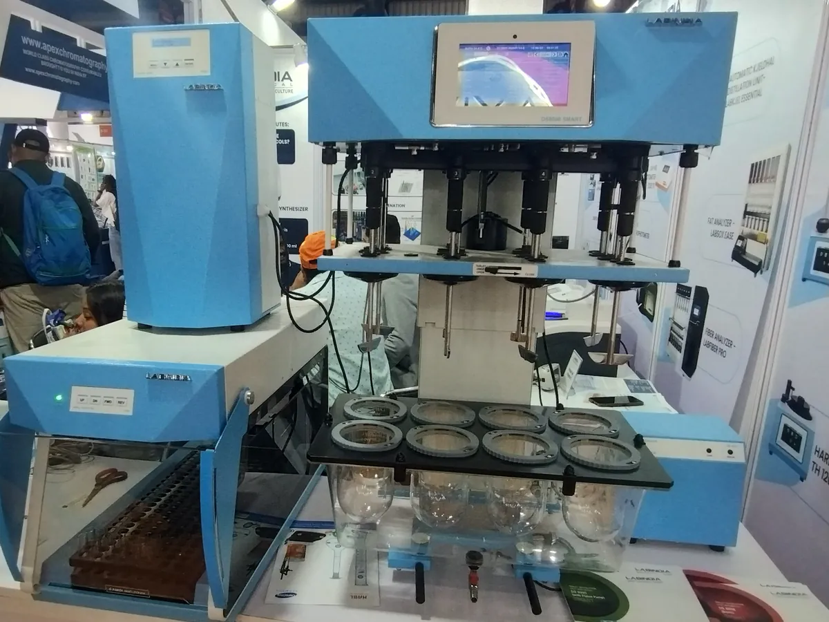
Why this is checked
Dissolution results depend on the flow pattern in the vessel. A shaft that wobbles, a vessel that is off-centre or tilted, or a paddle set at the wrong height all change the hydrodynamics and therefore the result. Mechanical calibration removes these sources of variability.
Typically every 6 months, and whenever vessels, shafts, paddles or baskets are changed or the apparatus is moved, as defined in your calibration SOP.
Learn how the Dissolution tester worksStandards & tools
- Calibrated shaft wobble gauge (dial indicator, 0.01 mm resolution)
- Calibrated digital level or inclinometer for shaft and vessel verticality
- Calibrated centring gauge (dial or digital)
- Calibrated height gauge or 25 mm depth gauge / ball
- Basket wobble gauge for apparatus 1
Prerequisites
- Apparatus on a level, vibration-free bench; check the vessel plate is level
- Vessels, paddles and baskets clean, undamaged and labelled by position
- Each vessel seated firmly in its own centring ring
Step by step
- 1Check the base plate and drive head are level using the digital level.
- 2Shaft wobble: mount the dial indicator against the rotating shaft (paddle or basket shaft) at the point stated in the SOP and record the total runout while it turns.
- 3Basket wobble (apparatus 1): fit a basket and measure runout at its lower rim.
- 4Shaft verticality: place the level against the shaft in two directions at 90° and record the deviation from vertical.
- 5Vessel verticality: place the level against the inside wall of each vessel in two directions at 90°.
- 6Centring: insert the centring gauge on the shaft and rotate it around the vessel wall near the top and near the bottom of the cylindrical part; record the maximum offset from the centre line.
- 7Height: lower the paddle or basket until the gauge just touches the vessel bottom and set the blade or basket bottom at 25 ± 2 mm; record the measured value.
- 8Repeat for every position and record all results.
Example observation table
| Position | Shaft wobble (mm) | Shaft verticality (°) | Vessel verticality (°) | Centring (mm) | Paddle height (mm) |
|---|---|---|---|---|---|
| 1 | 0.20 | 0.2 | 0.4 | 0.5 | 25.1 |
| 2 | 0.15 | 0.1 | 0.5 | 0.4 | 24.8 |
| 3 | 0.25 | 0.2 | 0.3 | 0.6 | 25.4 |
| 4 | 0.18 | 0.1 | 0.6 | 0.3 | 25.0 |
| 5 | 0.22 | 0.3 | 0.4 | 0.7 | 24.6 |
| 6 | 0.30 | 0.2 | 0.5 | 0.5 | 25.2 |
How to calculate the result
- Position 3 paddle height measured 25.4 mm
- Deviation = 25.4 − 25.0 = +0.4 mm (within ±2 mm)
- Position 6 shaft wobble 0.30 mm (within a typical 1.0 mm total runout limit)
Pass if
- Paddle or basket height: 25 ± 2 mm from the inside bottom of the vessel.
- Shaft wobble and basket wobble: typically not more than 1.0 mm total runout.
- Shaft verticality: typically within 0.5° of vertical; vessel verticality typically within 1.0°.
- Centring: USP requires the shaft axis within 2 mm of the vessel axis; enhanced (ASTM/FDA-style) procedures commonly use 1.0 mm.
- Apply the exact limits in your SOP and the current chapter.
What to do
- Label the position or the whole apparatus 'Out of calibration' and do not use it.
- Adjust or replace the vessel, centring ring, shaft or paddle as needed, then repeat the measurement.
- If a bent shaft or damaged paddle is found, assess dissolution results generated since the last passing calibration.
Other Dissolution tester calibrations
LimsPulse schedules this calibration, records the result against limits, and blocks the instrument everywhere if it fails or goes overdue.