PM sampler · Calibration procedure
Flow rate calibration
Checks and adjusts the sampler's flow rate against a calibrated flow transfer standard so the inlet cut-point and the sampled air volume are correct.
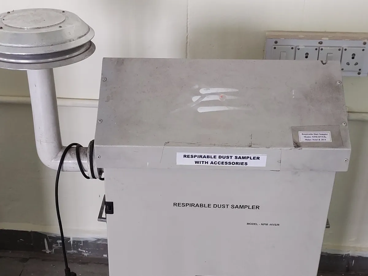
PURPOSE
Why this is checked
The PM concentration equals filter mass gain divided by air volume, so a flow error causes an equal error in the result. Flow also controls the inlet cut-point: if the flow is wrong, the sampler collects the wrong particle size range.
Frequency
Typically a single-point flow check monthly (or as required by the monitoring programme) and a multi-point calibration on installation, after repairs and at least annually, as defined in your SOP.
Learn how the PM sampler worksYOU WILL NEED
Standards & tools
- Certified flow transfer standard (for example a calibrated orifice for high-volume samplers, or a volumetric or mass flow calibrator for low-volume samplers), traceable to national standards
- Calibrated thermometer and barometer for ambient temperature and pressure
BEFORE YOU START
Prerequisites
- Sampler leak check passed
- A clean filter (or the type of filter used in sampling) installed
- Ambient temperature and pressure sensors of the sampler checked
PROCEDURE
Step by step
- 1Install a clean filter and connect the transfer standard to the inlet using the adapter.
- 2Run the sampler at its design flow (for example 16.67 L/min for a low-volume PM2.5 sampler) and allow it to stabilise.
- 3Record the sampler's indicated flow and the transfer standard flow, with ambient temperature and pressure.
- 4For a multi-point calibration, repeat at several flow points around the design flow and fit the calibration line.
- 5Calculate the difference between indicated and standard flow, and between standard flow and design flow.
- 6Adjust the sampler calibration if needed and repeat the check.
RECORD
Example observation table
| Check | Indicated flow (L/min) | Transfer standard flow (L/min) | Indicated vs standard (%) | Standard vs design 16.67 L/min (%) |
|---|---|---|---|---|
| As found | 16.67 | 16.41 | +1.58 | −1.56 |
| As left (after adjustment) | 16.67 | 16.52 | +0.91 | −0.90 |
CALCULATION
How to calculate the result
Formula
Flow difference (%) = (indicated − standard) ÷ standard × 100; Design flow error (%) = (standard − design) ÷ design × 100
Worked example
- 1As found: (16.67 − 16.41) ÷ 16.41 × 100 = +1.58%
- 2Design error: (16.41 − 16.67) ÷ 16.67 × 100 = −1.56%
- 3Both within typical limits, but adjusted to bring closer: (16.67 − 16.52) ÷ 16.52 × 100 = +0.91%
ACCEPTANCE CRITERIA
Pass if
- Indicated flow typically within ±4% of the transfer standard flow (as given in common reference method guidance; use your SOP)
- Measured flow typically within ±5% of the design flow rate
- Leak check passes the manufacturer's criterion
IF IT FAILS
What to do
- Do not start a sampling run until the flow passes.
- Check for leaks, a blocked inlet or a wrong filter, then repeat.
- Recalibrate the flow sensor or service the pump.
- Assess or invalidate runs since the last passing check where the flow error affects data.
In LimsPulse · Calibration Management
LimsPulse schedules this calibration, records the result against limits, and blocks the instrument everywhere if it fails or goes overdue.