Temperature and load verification
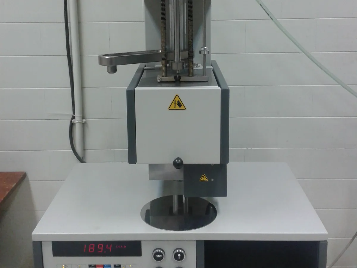
Checks that the melt temperature near the die matches the set point and that each piston-plus-weight combination gives the nominal load. Die bore and length are checked at the same time.
Why this is checked
MFR changes by several per cent for each degree of temperature error, and in proportion to the load. A worn die also raises the result. Verifying temperature, load and die dimensions against traceable standards makes MFR results comparable with suppliers and customers.
Typically every 6–12 months, after repair or die replacement, and when control-polymer results drift, as defined in your SOP.
Learn how the MFI tester worksStandards & tools
- Calibrated reference thermometer (platinum resistance probe or thermocouple with readout) that fits the barrel bore
- Calibrated balance or force-measuring device suitable for the piston and weights (for example 0.1 g readability for weights up to several kg)
- Die bore go/no-go gauge pins and a calibrated length gauge or micrometer
- Reference polymer with an assigned MFR (for overall performance check)
Prerequisites
- Barrel, die and piston clean
- Instrument at the test temperature and stabilised for at least about 15 minutes
- Reference thermometer and balance within calibration
Step by step
- 1Set the barrel to the first test temperature (for example 190 °C) and allow it to stabilise.
- 2Insert the reference probe into the barrel so its sensing tip is at the position the standard specifies (near the die, for example about 10 mm above the die top).
- 3Record the reference temperature and controller display every few minutes for about 30 minutes and calculate the mean and spread.
- 4Repeat at other temperatures used routinely (for example 230 °C).
- 5Weigh the piston alone and each piston-plus-weight combination used (for example 2.16 kg and 5 kg).
- 6Check the die bore with go/no-go gauges and measure die length.
- 7Run the reference polymer and compare its MFR with the assigned value.
Example observation table
| Check | Nominal | Measured | Error | Tolerance (typical) | Result |
|---|---|---|---|---|---|
| Temperature at die, set 190 °C | 190.0 °C | 190.2 °C (mean) | +0.2 °C | about ±0.5 °C | Pass |
| Temperature at die, set 230 °C | 230.0 °C | 229.8 °C (mean) | −0.2 °C | about ±0.5 °C | Pass |
| Load: piston + weight | 2160.0 g | 2160.9 g | +0.04% | ±0.5% | Pass |
| Load: piston + weight | 5000.0 g | 5003.1 g | +0.06% | ±0.5% | Pass |
| Die bore | 2.095 mm | 2.097 mm | +0.002 mm | ±0.005 mm | Pass |
| Die length | 8.000 mm | 8.010 mm | +0.010 mm | ±0.025 mm | Pass |
How to calculate the result
- 1
Temperature at 190 °C: readings 190.1, 190.2, 190.3, 190.2 °C → mean 190.2 °C → error = 190.2 − 190.0 = +0.2 °C
- 22.16 kg load: (2160.9 − 2160.0) ÷ 2160.0 × 100 = +0.04%
- 35 kg load: (5003.1 − 5000.0) ÷ 5000.0 × 100 = +0.06%
Pass if
- Temperature at the measuring position within the tolerance in the current ISO 1133 / ASTM D1238 edition (typically within about ±0.5 °C, with tighter stability over time)
- Combined piston and weight mass typically within ±0.5% of nominal
- Die bore typically 2.095 ± 0.005 mm and length 8.000 ± 0.025 mm
- Reference polymer MFR within its assigned range
What to do
- Label the instrument out of calibration and stop reportable tests.
- Adjust the controller offset if allowed, or have the sensor or heater serviced.
- Replace a die that is oversize or a weight that is out of tolerance.
- Assess MFR results reported since the last good check and retest retained samples if needed.
LimsPulse schedules this calibration, records the result against limits, and blocks the instrument everywhere if it fails or goes overdue.