Verification with a certified reference material
Tests a certified flash point reference material in the same way as a sample and checks that the corrected result falls within the tolerance on the certificate.
Why this is checked
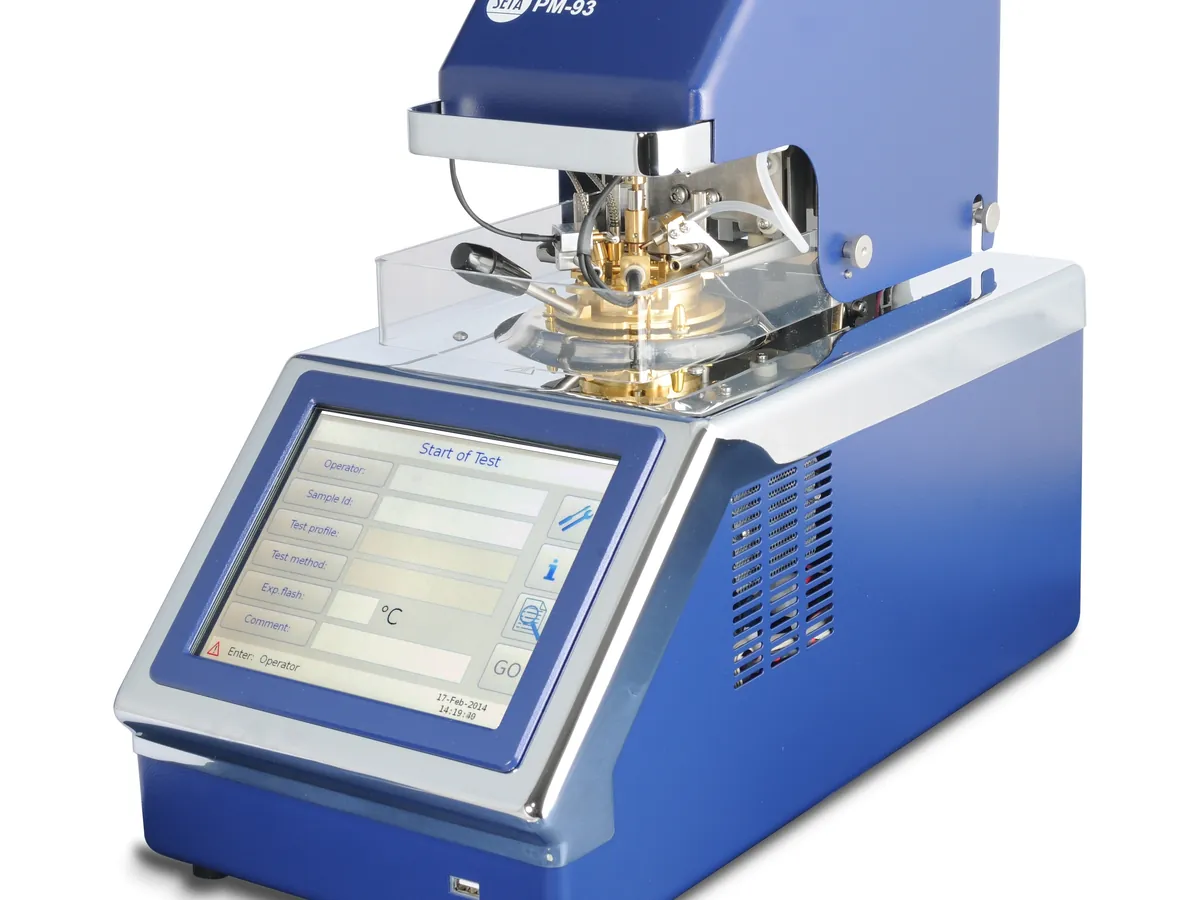
A flash point tester has many parts that affect the result: temperature sensor, heating rate, stirrer speed, ignition source size and timing, flash detector and barometer. Testing a certified reference material (CRM) checks all of them together. ASTM D93 and ISO 2719 both describe verifying the apparatus with reference materials of known flash point.
Typically monthly or per your SOP, after maintenance or part replacement, and whenever a check sample goes out of control.
Learn how the PMCC tester worksStandards & tools
- Certified flash point reference material with a value close to the range normally tested (pure hydrocarbon or blended verification fluid), with certificate and uncertainty
- Calibrated barometer (or the instrument barometer, itself verified)
- Optionally a second CRM at a higher flash point to cover the working range
Prerequisites
- Temperature sensor calibration in date
- Cup, lid, shutter and stirrer clean and dry
- Tester in a draught-free location
- CRM within its expiry date, stored cool and sealed
Step by step
- 1Allow the CRM bottle to reach room temperature unopened if it was refrigerated, then mix gently.
- 2Select the procedure stated on the certificate (usually Procedure A) and enter the certified value as the expected flash point.
- 3Fill the cup to the mark with CRM, fit the lid and run the test exactly as for a sample.
- 4Record the observed flash point and the barometric pressure.
- 5Correct to 101.3 kPa: corrected = observed + 0.25 × (101.3 − P).
- 6Repeat as your SOP requires (for example duplicate or triplicate) using fresh portions, and compare the mean corrected value with the certified value and tolerance.
- 7Plot the result on the control chart for the instrument.
Example observation table
| Run | Observed (°C) | Pressure P (kPa) | Correction (°C) | Corrected (°C) |
|---|---|---|---|---|
| 1 | 51.0 | 97.6 | +0.925 | 51.9 |
| 2 | 51.5 | 97.6 | +0.925 | 52.4 |
| 3 | 51.0 | 97.6 | +0.925 | 51.9 |
| Mean | 52.1 |
How to calculate the result
- 1
Illustrative certificate: 52.5 °C, tolerance ±2.0 °C.
- 2
Correction = 0.25 × (101.3 − 97.6) = 0.25 × 3.7 = 0.925 °C.
- 3
Corrected runs: 51.0 + 0.925 = 51.9 °C; 51.5 + 0.925 = 52.4 °C; 51.0 + 0.925 = 51.9 °C (to 0.1 °C).
- 4Mean = (51.925 + 52.425 + 51.925) ÷ 3 = 52.09 ≈ 52.1 °C.
- 5
Deviation = 52.1 − 52.5 = −0.4 °C, which is within ±2.0 °C — pass.
Pass if
- Mean corrected result within the tolerance stated on the CRM certificate (often derived from the method reproducibility).
- Individual results agree within the method repeatability.
- Result within control-chart limits; no unexplained trend.
What to do
- Clean and dry the cup thoroughly and repeat with a fresh CRM portion.
- Check heating rate, stirrer speed, ignition source size and timing, and flash detector position.
- Check the temperature sensor and barometer against references.
- Label the tester 'Out of calibration', stop reporting results and assess samples tested since the last good check.
LimsPulse schedules this calibration, records the result against limits, and blocks the instrument everywhere if it fails or goes overdue.