Gel electrophoresis · Calibration procedure
Power supply voltage and current check
Compares the voltage and current shown on the electrophoresis power supply with readings from a calibrated multimeter, using a known resistive load.
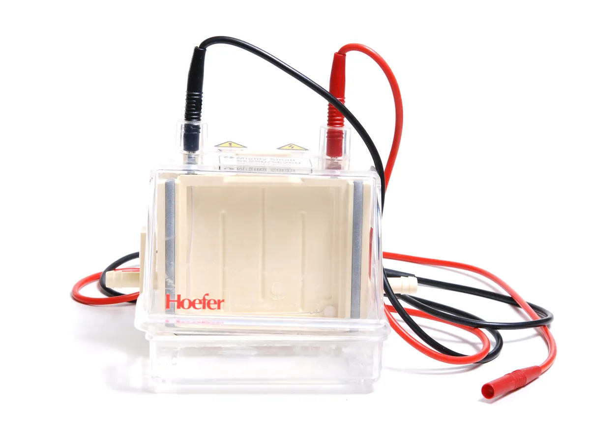
PURPOSE
Why this is checked
Migration rate and band resolution depend on the field strength. If the power supply output differs from its display, gels run faster or slower than validated, and heating changes. The check also confirms the timer and safety cut-outs work.
Frequency
Typically every 12 months and after repair, as defined in your SOP.
Learn how the Gel electrophoresis worksYOU WILL NEED
Standards & tools
- Calibrated digital multimeter rated for the voltage range (for example up to 1000 V DC), traceable to national standards
- High-voltage resistive load of known value (for example 1 kΩ, rated for the power used) or the supplier's test load
- Calibrated stopwatch for the timer check
BEFORE YOU START
Prerequisites
- Only trained staff perform the check; high voltage present
- Leads, connectors and insulation inspected and undamaged
- Test load and meter within calibration
PROCEDURE
Step by step
- 1Connect the power supply output to the test load with the meter connected in parallel to read voltage.
- 2Set constant voltage at several points across the used range (for example 50, 100, 200, 300 V), let it settle and record display and meter values.
- 3Connect the meter in series (or use a calibrated current shunt) to read current. With a known load, the expected current is I = V ÷ R.
- 4Record displayed current and measured current at each point.
- 5Check the timer against a stopwatch over at least 10 minutes.
- 6Confirm the power supply stops on open circuit (lead disconnected) as designed.
RECORD
Example observation table
| Set voltage (V) | Meter voltage (V) | Error (%) | Expected current (mA) | Measured current (mA) | Error (%) |
|---|---|---|---|---|---|
| 50 | 50.3 | +0.60 | 50.0 | 50.2 | +0.40 |
| 100 | 100.6 | +0.60 | 100.0 | 99.6 | −0.40 |
| 200 | 199.1 | −0.45 | 200.0 | 200.9 | +0.45 |
| 300 | 298.4 | −0.53 | — | — | — |
CALCULATION
How to calculate the result
Formula
Voltage error (%) = (measured − set) ÷ set × 100; Expected current (mA) = V ÷ R × 1000; Current error (%) = (measured − expected) ÷ expected × 100
Worked example
- 1At 200 V: error = (199.1 − 200) ÷ 200 × 100 = −0.45%
- 2With a 1000 Ω load at 100 V, expected current = 100 ÷ 1000 × 1000 = 100.0 mA
- 3Measured 99.6 mA → error = (99.6 − 100.0) ÷ 100.0 × 100 = −0.40%
ACCEPTANCE CRITERIA
Pass if
- Voltage and current typically within about ±1–2% of set value (or the manufacturer's stated accuracy, whichever your SOP specifies)
- Timer within about ±1% or as specified
- Safety cut-out (open circuit / overload) operates
IF IT FAILS
What to do
- Label the power supply out of use.
- Repair or adjust through the supplier and repeat the check.
- Assess recent gels for impact (for example altered migration or resolution).
In LimsPulse · Calibration Management
LimsPulse schedules this calibration, records the result against limits, and blocks the instrument everywhere if it fails or goes overdue.