Load verification with a proving ring or load cell
Compares the force shown by the CTM with the true force measured by a calibrated proving ring or reference load cell at several points across each range, and classifies the machine.
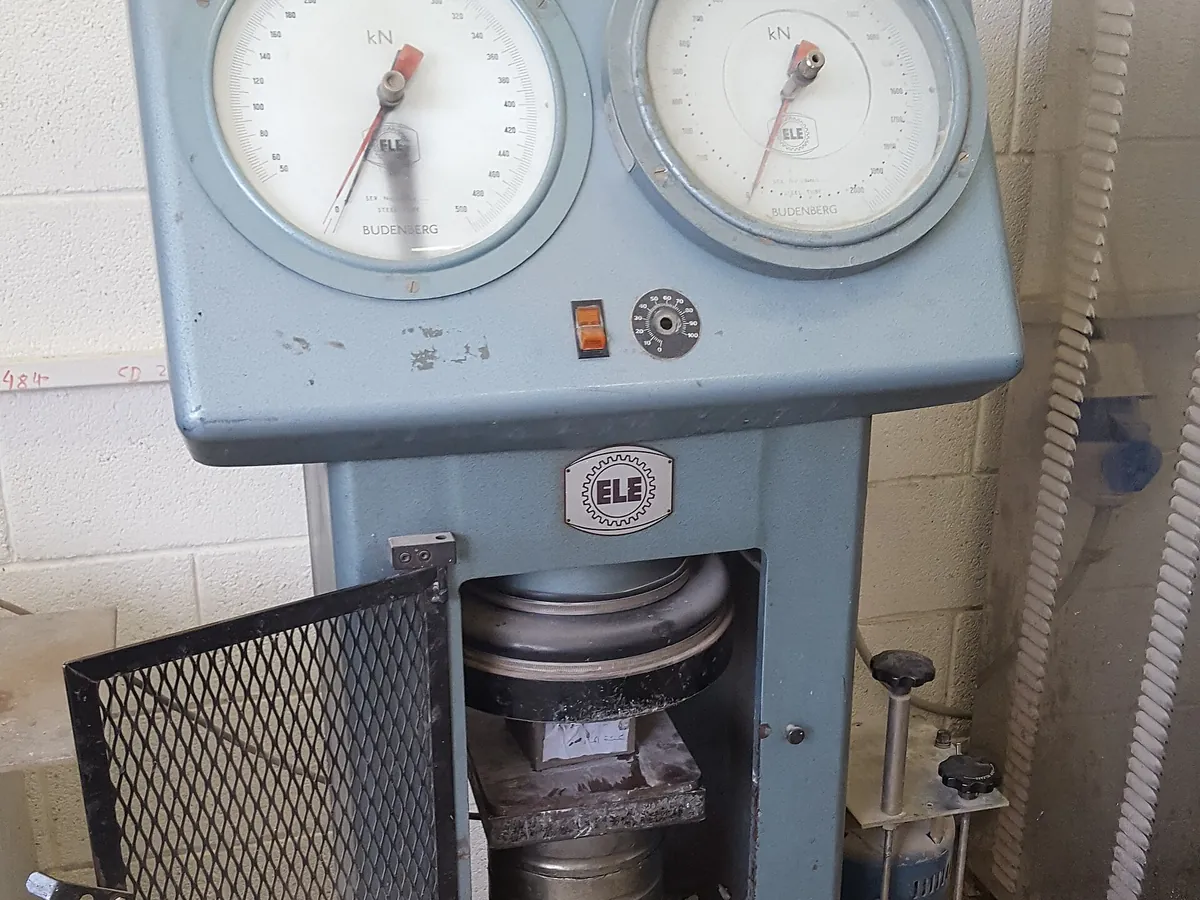
Why this is checked
Every compressive strength result is load ÷ area, so an error in the load reading goes straight into the strength. Verification shows the machine's relative error of indication and repeatability, and confirms it meets its class (usually Class 1 or better) over the verified range.
Typically every 12 months, and after repair, relocation, or replacement of the load sensor or display, as defined in your SOP or accreditation requirements.
Learn how the CTM worksStandards & tools
- Proving ring or reference load cell with a current calibration certificate traceable to national standards (calibrated to ISO 376 or ASTM E74, or the equivalent IS)
- Reference instrument class better than the class being verified (e.g. Class 0.5 or 00 reference for a Class 1 machine)
- Calibrated thermometer to record ambient temperature
- Steel spacers and centring plates
Prerequisites
- Machine switched on and warmed up as the manufacturer advises
- Platens clean; spherical seat free
- Reference device acclimatised to room temperature
- Machine pre-loaded at least three times to its maximum range (or to the maximum of the reference device) to seat the system
Step by step
- 1Place the proving ring or load cell centrally on the lower platen using centring plates; zero both the machine and the reference.
- 2Choose at least five force levels roughly evenly spaced from about 20% to 100% of the range being verified (add lower points if the verified range must extend lower).
- 3Apply force slowly and steadily. At each level, record the machine reading and the reference reading (either set the machine to a nominal force and read the reference, or set the reference to the nominal force and read the machine).
- 4Complete three series of increasing force; rotate the reference device (e.g. by about 120°) between series as the standard requires.
- 5After unloading, record any residual zero reading.
- 6Calculate mean indicated force, relative error of indication (q) and relative repeatability (b) at each level; compare with the class limits.
- 7Issue a certificate stating the class and verified range; label the machine.
Example observation table
| Reference force F (kN) | Machine run 1 (kN) | Run 2 (kN) | Run 3 (kN) | Mean (kN) | q (%) | b (%) |
|---|---|---|---|---|---|---|
| 400 | 402.8 | 404.0 | 403.2 | 403.33 | +0.83 | 0.30 |
| 800 | 806.4 | 805.2 | 807.0 | 806.20 | +0.78 | 0.22 |
| 1200 | 1209.6 | 1208.4 | 1210.8 | 1209.60 | +0.80 | 0.20 |
| 1600 | 1612.0 | 1614.4 | 1613.2 | 1613.20 | +0.83 | 0.15 |
| 2000 | 2016.0 | 2014.0 | 2018.0 | 2016.00 | +0.80 | 0.20 |
How to calculate the result
- 1
At 1200 kN: machine readings 1209.6, 1208.4 and 1210.8 kN
- 2Mean = (1209.6 + 1208.4 + 1210.8) ÷ 3 = 1209.60 kN
- 3q = (1209.60 − 1200) ÷ 1200 × 100 = +0.80%
- 4b = (1210.8 − 1208.4) ÷ 1200 × 100 = 0.20%
- 5
Largest |q| across all points = 0.83% and largest b = 0.30%, so the machine meets Class 1 (about ±1.0%) but not Class 0.5 (about ±0.5%).
Pass if
- Class 1 (the usual minimum for concrete testing): relative error of indication within about ±1.0% and relative repeatability within about 1.0% at every point of the verified range (IS 1828 Part 1 / ISO 7500-1).
- ASTM E4: indicated forces within ±1.0% of the true force across the verified range.
- Zero return and resolution within the limits given for the class.
What to do
- Label the machine 'Out of calibration' and stop reporting results from it.
- Have the load system adjusted by the manufacturer or a competent service provider, then repeat the full verification.
- Assess results issued since the last satisfactory verification and record the impact assessment.
- If the machine meets only a lower class, restrict its use to tests that permit that class.
LimsPulse schedules this calibration, records the result against limits, and blocks the instrument everywhere if it fails or goes overdue.